ROBOTICS · MECHANICAL DESIGN · MECHATRONICS
PROJECT / 01
6-DOF Robotic Arm
From actuator proof-of-concept to complete robotic system.
The project began as a 2-DOF platform for developing and testing custom robotic actuators. After designing, manufacturing and experimentally comparing cycloidal and planetary architectures, I selected the cycloidal design and completed a manufacturing-focused redesign for CNC production. From there, the project evolved into a complete 6-DOF robotic arm integrating custom mechanical design, FDM prototyping, electronics, kinematics and MATLAB-based motion control.

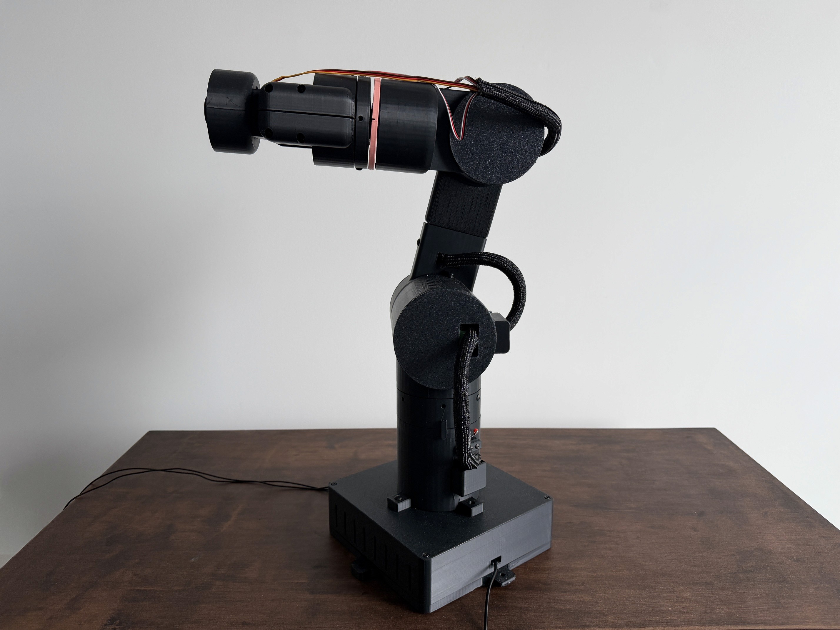
FINAL PROTOTYPE / 6-DOF ROBOTIC SYSTEM
6 DOF
ROBOTIC SYSTEM
650 mm
MAXIMUM REACH
0.5 kg
Design PAYLOAD
MATLAB
KINEMATICS + CONTROL
PROJECT TYPE
Independent Engineering Project
ROLE
Mechanical Design · Manufacturing · Electronics · Control
PRIMARY TOOLS
SolidWorks · MATLAB · FDM Manufacturing
DEVELOPMENT
2 DOF → 3 DOF → 5 DOF → 6 DOF
DESIGN OBJECTIVE / 01
Proving the actuator could be the foundation for a complete robotic system
The project began as a 2-DOF actuator proof of concept, then expanded into a six-axis system as each mechanical, packaging and control challenge was validated.
2 DOF → 3 DOF → 5 DOF → 6 DOF
PROOF OF CONCEPT → COMPLETE ROBOTIC SYSTEM
DESIGN Requirements
01 — WORKSPACE
Coffee-Table-Scale
Keep the robot compact enough for a desktop-scale workspace while still providing useful reach.
02 — PAYLOAD
≥0.5 kg Target
Design around a minimum 0.5 kg payload in the arm's extended configuration.
03 — MANUFACTURING
Predominantly FDM
Design the custom mechanical components around FDM manufacturing so parts could be produced, tested and revised quickly.
04 — SYSTEM INTEGRATION
Mechanical + Electronic + Control
Integrate the structure, actuators, electronics and control system into one functioning robot rather than treating each subsystem independently.
DESIGN CONSTRAINTS
FDM MANUFACTURING
COMPACT PACKAGING
MOVING MASS
CABLE & ELECTRONICS INTEGRATION
DESIGN EVOLUTION / 02
From 2 DOF proof of concept to a complete 6-DOF system.
The robot was developed incrementally rather than designed as a complete six-axis system from the start. Each prototype introduced new mechanical, packaging and control challenges that informed the next iteration.
01
2 DOF
ACTUATOR PROOF OF CONCEPT
Built the initial platform to determine whether the custom cycloidal actuator could function successfully as a robotic joint.
02
3 DOF
EXPANDED ARM
Added another actuated joint and began developing the link and joint architecture into a serial robotic arm.
03
5 DOF
WRIST INTEGRATION
Added wrist articulation, introducing new packaging, distal-mass and actuator-integration challenges.
04
6 DOF
COMPLETE SYSTEM
Integrated six controlled axes with homing, electronics, kinematics and coordinated physical motion.
INCREASING SCOPE, INCREASING INTEGRATION
Each additional degree of freedom introduced new mechanical, packaging and control requirements. By the final iteration, the project had evolved from validating a single actuator concept into integrating a complete robotic system.
FEATURED ITERATION / WRIST ARCHITECTURE
Packaging three rotational axes into a compact spherical wrist.
Earlier wrist designs were relatively long and placed more mass farther from the upstream joints. I redesigned the wrist into a shorter three-axis architecture with the rotational axes intersecting at a common point.

From bulky packaging to a compact three-axis spherical wrist.
REDUCED DISTAL LENGTH
Shortened the wrist assembly to reduce the moment arm of the distal components and payload.
3-AXIS SERVO PACKAGING
Packaged three 0–270° 25 kg·cm servos into the wrist for pitch, yaw and roll.
INTERSECTING ROTATIONAL AXES
Arranged the three wrist axes to intersect at a common point, creating a spherical wrist architecture.
PITCH
YAW
ROLL
SPHERICAL WRIST , THREE ROTATIONAL AXES INTERSECT AT A COMMON POINT
DESIGN RATIONALE — Reducing distal length decreases the moment arm of the wrist and payload, reducing static torque demand on upstream joints.
3 AXES
PITCH · YAW · ROLL
3 × 25 kg·cm
SERVO ACTUATION
0–270°
SERVO RANGE
COMMON POINT
INTERSECTING AXES
MECHANICAL ARCHITECTURE / 03
Six axes. Two actuation approaches. One integrated mechanical system.
The final robot combines three custom cycloidal-driven primary joints with a compact three-servo spherical wrist. I designed the links, actuator housings, shafts, supports, wrist structure and mounting components around this architecture, while bearings, motors, electronics, limit switches and other standard hardware were sourced off the shelf.
FINAL ROBOT ASSEMBLY / ANNOTATED CAD


J1 — BASE
J2 — SHOULDER
J3 — ELBOW
J4 — WRIST PITCH
J5 — WRIST YAW
J6 — WRIST ROLL


PRIMARY ARM
BASE · SHOULDER · ELBOW
3 × Custom Cycloidal Joints

NEMA 17 stepper motors with Servo42C closed-loop drivers actuate the three primary joints through approximately 20:1 custom cycloidal reductions.
NEMA 17 · CLOSED LOOP · CYCLOIDAL REDUCTION · FDM HOUSINGS
SPHERICAL WRIST
PITCH · YAW · ROLL
3 × 25 kg·cm Servos

Three 0–270° servos provide wrist pitch, yaw and roll through a compact architecture with intersecting rotational axes.
0–270° SERVOS · 3 ROTATIONAL AXES · INTERSECTING AXES · COMPACT PACKAGING
SYSTEM DEFINITION / BILL OF MATERIALS
What went into the final build.
The final robot combines custom FDM components with off-the-shelf actuators, bearings, fasteners and electronics. I designed the custom mechanical components around the purchased hardware, with the complete assembly documented in a component-level BOM.
01 / PRIMARY ACTUATION
3 Custom Joint Actuators
NEMA 17 · Closed-loop control · ~20:1 cycloidal reduction
BASE · SHOULDER · ELBOW
02 / WRIST
3-Axis Spherical Wrist
3 × 25 kg·cm servos · Pitch · Yaw · Roll
CUSTOM FDM WRIST STRUCTURE
03 / CONTROL + POWER
Motion Control System
MKS TinyBee · 24 V system · Servo power conversion · Homing switches
04 / STRUCTURE + HARDWARE
Custom Mechanical Assembly
Custom FDM Components — Links · housings · actuator components...
DESIGNED + ASSEMBLED IN-HOUSE
WEBSITE BOM / KEY COMPONENTS
Component-level breakdown.
The condensed BOM below highlights the primary mechanical, actuation, control and power components used in the final six-axis system.
SUBSYSTEM
COMPONENT
KEY SPECIFICATION
QTY.
J1–J3 Actuation
NEMA 17 Stepper Motor
SIMAX3D, 42×40 mm, 1.5 A, 1.8°/step
3
J1–J3 Actuation
Cycloidal Gearbox Components
Dual cycloidal discs, eccentric drive & output stages
3 sets
J1–J3 Actuation
Cycloidal Drive Bearings
MR6701-2RS, MR6704-2RS & 6806-2RS
24
J1–J3 Actuation
Output Bushings
7×10×8 mm self-lubricating sintered bronze
34
J4–J6 Wrist
DS3225MG Servo
25 kg·cm
3
J4–J6 Wrist
Custom Wrist Gearing
M1 & M0.5 FDM spur/internal gears
5
J4–J6 Wrist
6810-2RS Bearings
50×65×7 mm
2
J4–J6 Wrist
GT2 Belt Drive
20T + 40T aluminum pulleys; 2 mm-pitch belt
1 set
Structure
Custom FDM Components
PLA; links, housings, flanges, couplers, wrist & end-effector components
Various
Control
MKS TinyBee V1.0
12–24 V main control board
1
Control
Closed-Loop Stepper Drivers
Servo42C closed-loop drivers
3
Control
Roller-Lever Limit Switches
SPDT homing switches
3
Power
DC Bench Power Supply
Jesverty SPS-3010M, 0–30 V / 0–10 A
1
Power
DC-DC Buck Converter
12/24 V → 6 V, 10 A, 60 W
1
Power
Power Distribution
4-way distribution blocks + terminal blocks
4
Wiring
Servo Extension Cables
3-pin, 600 mm
3
Wiring
Power & Signal Wiring
20 AWG silicone wire, ferrules & fork terminals
As req.
Hardware
Metric Fasteners & Inserts
M2–M5 screws + brass heat-set inserts
Various
18 condensed entries shown · Full component-level BOM available
DESIGNED IN SOLIDWORKS
Custom mechanical design
6 POWERED AXES
3 cycloidal + 3 servo
MKS TINYBEE
Central motion controller
PREDOMINANTLY FDM
Custom mechanical components
DESIGN FOR MANUFACTURE
Built around additive manufacturing from the beginning.
FDM manufacturing was treated as a design constraint rather than simply a prototyping method. Component geometry, assembly clearances, print orientation, threaded interfaces and access to purchased hardware were considered throughout the design so parts could be manufactured, assembled and iterated quickly.
PRINTABLE GEOMETRY
Geometry designed around practical FDM constraints and printability.
FIT & CLEARANCE
Interfaces adjusted to account for printed dimensional variation and assembly fit.
ITERATIVE MANUFACTURE
Parts were repeatedly printed, assembled, tested and revised.
COMPONENT ACCESS
Housings and supports allowed motors, bearings, wiring and other hardware to remain serviceable.
FEATURED ENGINEERING CHALLENGE / SHOULDER JOINT
Iterating the shoulder actuator from binding to reliable motion.
The shoulder actuator exposed two problems that only became obvious during physical testing. A six-output-pin configuration caused the joint to bind completely, so I revised the output stage to five pins. I then iterated the printed clearances to find a workable fit between binding and excessive joint play.
01 / INITIAL TEST
6 Output Pins
Complete Binding
02 / GEOMETRY REVISION →
Output Stage
6 → 5 Pins
03 / FIT ITERATION →
Printed Clearances
Repeated Assembly + Testing
04 / FINAL RESULT
5 Output Pins
Functional Joint Motion
TOO TIGHT
Insufficient output-interface clearance
Binding and increased resistance through the actuator output.
ITERATION
Printed clearance adjustments
Output interfaces were revised through repeated printing, assembly and physical testing.
TOO LOOSE
Excessive output-interface clearance
Increased actuator movement and joint play.
BINDING ← TIGHT FIT
FUNCTIONAL OPERATING RANGE
LOOSE FIT → WOBBLE
DESIGN TAKEAWAY
The shoulder actuator required both geometry and fit adjustments. Reducing the output stage from six pins to five eliminated the initial binding condition, while repeated printing and assembly established a practical clearance between excessive resistance and joint play. The final fit was therefore determined through physical iteration rather than nominal CAD dimensions alone.
ENGINEERING ANALYSIS / 04
Design validation through engineering calculations.
Targeted engineering calculations were used to evaluate three aspects of the final design: available shoulder torque under the worst-case extended configuration, bending of the printed arm structure, and the reachable Tool Center Point workspace predicted by the robot’s kinematic model.
ANALYSIS 01 — WORST-CASE SHOULDER LOADING

WORST-CASE EXTENDED CONFIGURATION
shoulder axis · ≈220 mm first segment · ≈230 mm additional distance · 0.45 m total payload moment arm · downward payload force
SHOULDER TORQUE MODEL
Motor Torque
0.4 N·m
Shoulder Reduction
25:1
Assumed Drive Efficiency
75%
Estimated Available Output Torque
7.5 N·m
≈ 1.7 kg
ESTIMATED STATIC PAYLOAD CAPACITY
0.5 kg
SELECTED DESIGN PAYLOAD
≈ 3.4×
CALCULATED MARGIN VS. DESIGN PAYLOAD
The simplified static calculation estimated the payload capacity of the arm in its worst-case extended configuration from the available shoulder-joint torque and payload moment arm. A 0.5 kg design payload was selected, providing a calculated margin of approximately 3.4× relative to this simplified model.
STRUCTURAL CHECK / PRINTED LINK
Checking whether link strength was a limiting design factor.
LOAD / MATERIAL MODEL
PLA (simplified)
E = 3.0 GPa
Yield Strength = 50 MPa
b = 30 mm
h = 80 mm
c = 40 mm
BENDING MODEL
σ = Mc / I
I = bh³ / 12
SIMPLIFIED RESULTS
I ≈ 1.28 × 10⁻⁶ m⁴
Mmax ≈ 4.87 N·m
σ ≈ 0.15 MPa
δ ≈ 6.67 × 10⁻⁵ m
≈ 66.7 μm
RESULT
Gross link bending was not identified as the limiting structural issue under the evaluated static loading condition.
MATERIAL / MODEL LIMITATION
The calculation used a simplified PLA material assumption. Because FDM components are affected by print orientation, infill, layer bonding and manufacturing parameters, the result is treated as a preliminary structural check rather than a complete material-failure model.
KINEMATIC ANALYSIS / MATLAB
Mapping the reachable TCP workspace.
Coordinate frames and Denavit–Hartenberg parameters were established for the six-joint manipulator. The resulting forward-kinematic model was evaluated across the allowable ranges of the three primary positioning joints in MATLAB to map the three-dimensional region accessible to the Tool Center Point.

6-DOF KINEMATIC MODEL
Joint coordinate frames and DH parameters used to construct the forward-kinematic model.

REACHABLE TCP WORKSPACE
29,791
TCP POSITIONS SAMPLED
−388.96 → +388.96 mm
X RANGE
−387.56 → +387.56 mm
Y RANGE
32.29 → 591.21 mm
Z RANGE
Forward kinematics were evaluated across the permitted ranges of the three primary positioning joints while the wrist remained at its home configuration.
JOINT GEOMETRY → DH PARAMETERS → FORWARD KINEMATICS → JOINT-RANGE SAMPLING → 29,791 TCP POSITIONS → 3D REACHABLE WORKSPACE
KINEMATICS & CONTROL / 05
From Cartesian target to coordinated physical motion.
01 — CARTESIAN POSITIONING
Solving joint configurations from XYZ targets.
After homing establishes a known robot configuration, a desired Cartesian XYZ position is passed to the inverse-kinematics solver to determine a joint configuration within the defined joint limits.

INPUT / X · Y · Z TARGET
↓
SOLVE / INVERSE KINEMATICS
↓
OUTPUT / θ₁ · θ₂ · θ₃ · θ₄ · θ₅ · θ₆
02 — POSE VALIDATION
Checking the solution before commanding hardware.
The generated joint configuration is checked with forward kinematics and visualized in MATLAB before motion is approved.

TARGET POSITION / REQUESTED XYZ
IK → FK CHECK → POSE PREVIEW
VALIDATED POSE / MATLAB ROBOT VISUALIZATION
USER CONFIRMATION — Motion is transmitted only after the generated pose is accepted.
03 — CONTROL ARCHITECTURE
Connecting MATLAB control to the physical robot.
SOFTWARE / MATLAB
Cartesian XYZ Target
↓
IK Solution
↓
FK Validation
↓
Pose Approval
↓
Joint Commands
VALIDATED JOINT ANGLES
↓
SERIAL COMMAND
→
HARDWARE / MKS TINYBEE
PRIMARY JOINTS — NEMA 17 + Servo42C
WRIST JOINTS — 3 × SERVOS
↓
6-AXIS PHYSICAL MOTION
NEXT — ELECTRONICS & HOMING →
ELECTRONICS & HOMING / 06
Establishing control from power-up to a known robot state.
The electrical system integrates closed-loop stepper control for the primary joints, servo actuation for the wrist, mechanical limit switches for referencing, and the MKS TinyBee as the central motion controller. A defined homing sequence establishes the angular state of all six joints before Cartesian motion commands are executed.
01 — SYSTEM ELECTRONICS
One controller, two actuator systems.

MOTION CONTROLLER
MKS TinyBee
Receives coordinated serial commands from MATLAB and controls the physical joint actuators.
PRIMARY JOINT ACTUATION
NEMA 17 + Servo42C
Closed-loop stepper systems actuate the base, shoulder and elbow joints through the custom cycloidal transmissions.
WRIST ACTUATION
3 × 25 kg·cm Servos
0–270° servos actuate wrist pitch, yaw and roll.
POSITION REFERENCING
Mechanical Limit Switches
Physical reference points are used during startup to establish known joint positions.
Electrical schematic showing power distribution, controller connections, primary-joint stepper control, wrist servos and mechanical homing switches.
02 — POWER ARCHITECTURE
Separating the stepper and servo voltage requirements.
24 V POWER SUPPLY
PATH A — PRIMARY JOINTS
24 V
↓
STEPPER CONTROL SYSTEM
↓
NEMA 17 PRIMARY JOINT MOTORS
The primary-joint stepper drivers are supplied directly from the 24 V power rail.
PATH B — WRIST
24 V
↓
BUCK CONVERTER
↓
6.7 V
↓
3 × WRIST SERVOS
A buck converter reduces the supply voltage to 6.7 V for the wrist servos.
03 — POSITION REFERENCING
Turning an unknown startup configuration into known joint coordinates.
At power-up, the controller does not initially have a reliable absolute reference for the complete robot configuration. A defined homing sequence uses mechanical reference switches and commanded repositioning to establish known angular positions before Cartesian control is enabled.
01 — ELBOW REFERENCE
The elbow moves toward its mechanical limit switch.
SWITCH TRIGGERED
↓
The elbow reference is established.
↓
ELBOW → 180° ABSOLUTE
02 — SHOULDER REFERENCE
The shoulder moves toward its mechanical limit switch.
SWITCH TRIGGERED
↓
The shoulder reference is established.
03 — ARM REPOSITIONING
Once the shoulder has been referenced:
SHOULDER → 90°
ELBOW → 90°
KNOWN INTERMEDIATE CONFIGURATION
04 — BASE REFERENCE
The base rotates toward its mechanical limit switch.
SWITCH TRIGGERED
↓
The base reference is established.
05 — WRIST ZERO
Once the base homing sequence is complete, the three wrist servos move to their defined zero positions.
PITCH → 0°
YAW → 0°
ROLL → 0°
06 — HOMING COMPLETE
ALL 6 JOINT POSITIONS KNOWN
↓
ROBOT READY FOR CARTESIAN COMMANDS
The completed sequence establishes a known angular state for the full six-joint system, providing the reference configuration required by the MATLAB kinematic model and subsequent motion commands.
AT POWER-UP
Joint state unknown
→
AFTER HOMING
6 joint positions known
→
CONTROL ENABLED
Cartesian motion available
With all six joints referenced to known positions, the robot is ready to execute validated Cartesian commands.
NEXT — SYSTEM VALIDATION →
SYSTEM VALIDATION / 07
From calculated motion to a functioning physical system.
The completed robot was evaluated through physical operation to verify that the mechanical structure, joint actuators, homing system, electronics and MATLAB control workflow could operate together as an integrated 6-DOF system.
INTEGRATED SYSTEM DEMONSTRATION
01 — INTEGRATED MOTION
Integrated 6-DOF Motion
The completed robot demonstrates coordinated physical motion across all six controlled axes, integrating the mechanical structure, custom actuators, electronics, homing system and MATLAB-based control architecture.
6 CONTROLLED AXES
6 DOF
FINAL ARCHITECTURE
650 mm
ARM REACH
6 AXES
PHYSICAL CONTROL
MATLAB
MOTION CONTROL
VALIDATION SCOPE
Testing focused on functional system integration and commanded physical motion. Formal positional accuracy, repeatability, endurance and payload characterization were not performed and are therefore not claimed.
NEXT — FINAL SYSTEM & REFLECTION →
FINAL SYSTEM & REFLECTION / 08
From an actuator experiment to a complete robotic system.
The project began as a 2-DOF actuator proof of concept and developed into a complete 6-DOF robotic arm integrating mechanical design, FDM manufacturing, electronics, kinematics and control.

DESIGN REVIEW
A functional prototype also exposed opportunities for a second generation.
Completing the first functional system made it possible to evaluate architectural decisions that would be difficult to assess from CAD or calculations alone. A future version would use the current robot as a test platform for investigating alternative control, motor and transmission architectures.
01 — ROS 2 CONTROL INVESTIGATION
Move toward a robotics-focused control architecture.
More scalable robotics-focused control and motion planning.
CURRENT
MATLAB → Serial → MKS TinyBee
↓
V2 INVESTIGATION
ROS 2-Based Robot Control
02 — BLDC + FOC MOTOR INVESTIGATION
Investigate a different joint motor architecture.
Investigate a higher-performance joint motor and control architecture.
CURRENT
Closed-Loop NEMA 17
↓
V2 INVESTIGATION
BLDC + Field-Oriented Control
03 — ALTERNATIVE TRANSMISSION INVESTIGATION
Expand the gearbox trade study.
Evaluate harmonic/strain-wave or other gearbox architectures against the existing cycloidal approach.
CURRENT
Cycloidal Reduction
↓
V2 INVESTIGATION
Cycloidal · Strain-Wave / Harmonic-Style · Other Compact Reductions
NEXT ITERATION
CONTROL
Can ROS 2 provide a more scalable control and motion-planning architecture?
MOTOR
Can BLDC + FOC improve the useful torque-speed characteristics of the joints?
TRANSMISSION
Which reduction architecture provides the best balance of backlash, torque density, mass, packaging and manufacturability?
PROJECT TAKEAWAY
An idea became an actuator. The actuator became a prototype. The prototype became a robot.
The project demonstrated an iterative design-build-test process spanning mechanical design, manufacturing, electronics, kinematics and physical system integration.
DEEPER INTO THE ACTUATOR DESIGN
Custom Robotic Actuator Development →
Explore the cycloidal and planetary actuator development, mechanical design, manufacturing iterations and comparative testing that preceded the complete robotic system.